 Vaibhav Devnani
 If you are into electronics/arduinos you know how annoying it is to live with just 13 digital outputs, one way to deal with this is to get a microcontroller with more digital outputs but sometimes thats not feasible or even they are not enough.
In this article I will introduce you to shift registers, and how you can integrate them into your projects and get (pratically)unlimited digital inputs/outputs by just using 3 of your arduino pins. A shift register is an integrated circuit (IC) with eight digital output pins that can be controlled by sending a byte of data to the IC. Shift registers are the basic building blocks of daily electronics such as displays, calculators, digital clocks, keyboards etc.
For our projects, we will be using the 74HC595 shift register.
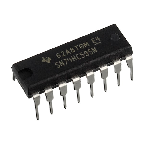
The 74HC595 shift register has eight digital outputs that can operate like the Arduino digital output pins. The shift register takes up three Arduino digital output pins. The principle behind the shift register is simple: We send 1 byte of data (8 bits) to the shift register, and it turns on or off the matching eight outputs based on the 1 byte of data.
A byte is a collection of 8 bits which are either 1 or 0. Most of us learn to count using th ebase-10 number system, but computers count using the base-2 also called the binary number system. Binary numbers consist of only 1s and 0s—for example, 10101010. In binary, each digit from right to left represents 2 to the power of the column number in which it appears (which increases from right to left). The products in each column are then added to determine the value of the number.
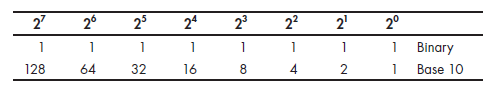
For example- 11010011=211 The bits representing the byte of data match the output pins in order from highest to lowest. So the leftmost bit of the data represents output pin 7 of the shift register, and the rightmost bit of the data represents output pin 0. For example, if we send B10000110 to the shift register, then it will turn on outputs 7, 2, and 1 and will turn off outputs 0 and 3–6 until the next byte of data is received.
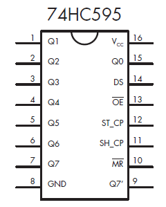
Pins 15 and 1 to 7 are the eight output pins that we control (labeled Q0 to Q7, respectively). Pin 9/Q7 is ‘data out’ and is used to send data to another shift register. This technique is called daisy chaining and it allows you to have unlimited digital outputs. I have included a tinkercad demo, here you can play with the circuit and also use the code in your further projects.
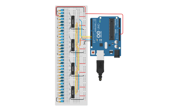
This basic use application can only control leds, although leds are fun but there are limits to kind of data tha can be displayed wth individual lights. Now we’ll see 7 segment displays in action with shift registers.
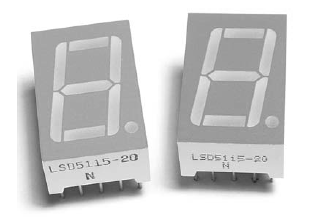
You must have seen these kind of displas on calculators, clocks and old electronics. These displays are perfect for displaying numbers.
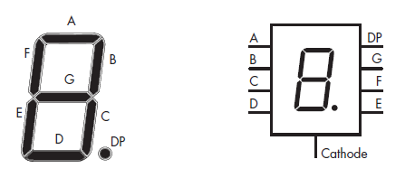
From the schematic you must have already figured out that the segments of the display are nothing but 8 leds with a common cathode. To use this you will require 8 arduino outputs but that is not feasible for your projects, so shift registers are used, and they are also daisy chained to control multiple 7 segment displays and create a large number display by use of just 3 arduino pins.
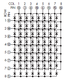
If you enjoyed experimenting with blinking LEDs, then you’re going to love LED matrix modules. An LED matrix module consists of several rows and columns of LEDs that you can control individually or in groups. These led matrix modules are the building bocks of your modern displays which you use in your phones, computers, watches, washing machines and what not.
The example shown has eight rows and eight columns of red LEDs for a total of 64 LEDs.
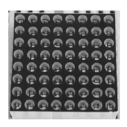
It is impossible to control 64 leds with a arduino, but when organised in rows and columns you just need to have 16 digital outputs to control each and every led.
You can daisy chain multiple displays like this and have a large led display. Going into further details about it’s working and tutorial on how to use this display is beyond the scope of this article and it will be a part of upcoming articles.
I hope you enjoyed learning about shiift registers and are planning to use these with your upcoming projects, don’t forget to share those with me I would to love to see them. I have attached 2 video tutorials from element14’s youtube channel on how to use shift register for outputs and also inputs.
How to Add Outputs to an #Arduino using a Shift Register - The Learning Circuit
How to Add Multiple Inputs to an #Arduino using a Shift Register - The Learning Circuit
I hope you liked the article, do reach out to me if you havae any suggestions/feedbacks. Subscribe to my newsletter if you want articles like these to be deliviered straight to your Inbox! Thank You!