 Vaibhav Devnani
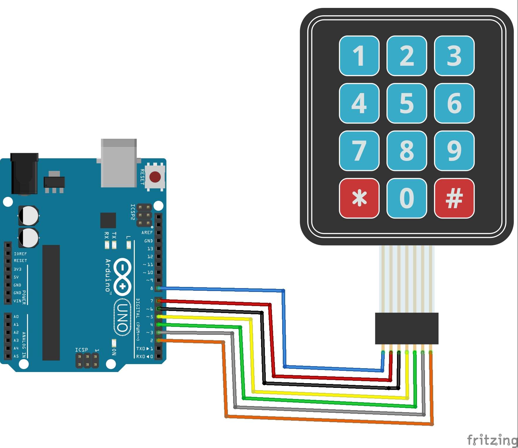
A 4*4 keypad like in the image below is very widely used in hobby projects, as it is a very inexpensive and easy way to add a input device to yoour projects.
But it has a major downside that it uses 8 of your digital outputss of your microcontroller, which is not feasible because you will be using several other electronics too with your project.
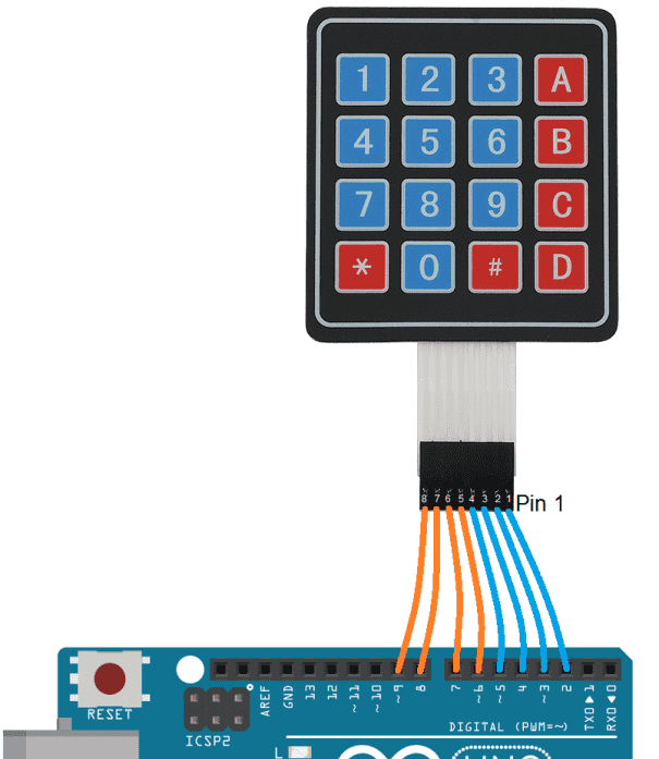
This keypad works just like the led matrix shown in the previous article, the buttons are arranged in rows and columns and each button has one terminal attached to the row line and one to the column line. When a button is pressed, it shorts the respective row and column and the arduino knows which button was pressed. Since, it is a 4*4 keypad it has 16 buttons and it uses 8 pins.
.jpg)
In this article, we will see a concept with which you can use this keypad by using just 1! of your arduino’s analog inputs.
The basic principle used in thiss technique is of a voltage divider/potential divider.
.jpg)
A very simple voltage divider using 2 resistors has been shown in the picture, it involves applying a constant voltage to a series of resistors and according to ohm’s law there will be voltage drop directly proportional to the value of resistance. This principle is used to divide a voltage into smaller parts as required. Potentiometers/rheostats also work on the same principle.
.jpg)
.jpg)
To use this principle with the keypad we create the following circuit, from the 2nd image you can see when button 6 is pressed row 1 is connected to col 2 now the circuit contains only r7, r6 and r10 in the bottom circuit creating a unique resistance and hence a unique voltage. Similarly for every button there will be a unique value of voltage generated which will be read by the arduino’s analog input. (r12 and c1 are present just as a debounce circuit.)
Now, for every button press you will get unique voltage read by the arduino, with these values you can use a dictionary or lists and map every button on the keypad. I agree the circuit is a bit bulky but if integrated in a pcb it can turn out to be very useful.
I have added a TinkerCAD demo I made below with the above circuit and arduino analog read, you can play around with it to see how it works.
.png)
Check out Hari Wiguna’s video demonstrating this in action.HariFun #143 - How to read a 4x4 keypad using just one Arduino pin!
I hope you liked the article, do reach out to me if you havae any suggestions/feedbacks. Subscribe to my newsletter if you want articles like these to be deliviered straight to your Inbox! Thank You!
 Shift Registers + Arduino = MAGIC!